
The idea of the Enhanced Vision Goggles
“Do we really see the world as it is?” Our Physics teacher, Mr. Hunt, asked our class this question, and then asked if anyone could think of an example of how we might be able to see things we normally can’t see. Someone said “how about night vision?” which sparked a discussion about how our class might be able to make our own night-vision glasses.
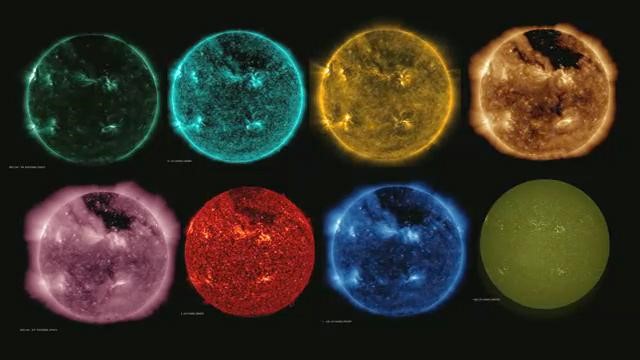
Mr. Hunt then showed us images of the sun from NASA’s Solar Dynamic Observatory at different wavelengths, which led to discussions of all the phenomena going on around us all the time that we are unaware of because our eyes can’t take in that information.
The idea of making simple night vision goggles quickly evolved into the possibility of broader vision enhancement, and this project of making goggles that would allow us to see in different parts of the electromagnetic spectrum that we can’t normally see was born.
Even though there are limits to what our natural human eyes can see, we can use cameras to capture the information we’re otherwise unaware of. Mr. Hunt initially suggested naming the project “Jordy Goggles,” but most of the class isn’t familiar with that Star Trek franchise, so we decided to call our class project “Enhanced Vision Goggles.”
Choosing the Right Type of Camera Modules
Once the idea of the enhanced vision goggles came into being, we had to decide what kind of components to use, especially what camera modules. Since the project’s aim is to “enhance vision” at different wavelengths like the NASA images above show, we need cameras that can capture images using multiple wavelength ranges.
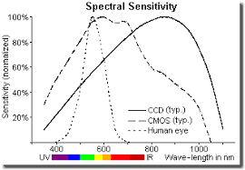
Most of the light sensors that are at the heart of modern digital cameras are sensitive in both the near UV and near IR ranges in addition to the visible spectrum. In order to make pictures that don’t look weird, modern digital cameras have filters in place that block the IR and UV our eyes can’t see. When we were initially just thinking about night vision, we had planned to use Arducam NoIR cameras which have an IR filter that can be automatically removed so that it can see IR light. We figured this is probably the most straightforward solution for both visible and IR spectral bands.
While this solution should make it relatively easy to deal with the IR and visible light, we still have to find an affordable way to capture images with UV light. The raw sensors in most consumer cameras are capable of absorbing both UV and IR, and if the graph below is representative, it should be possible to use a standard CMOS camera without the UV filtering system in place to capture a usable range of UV.
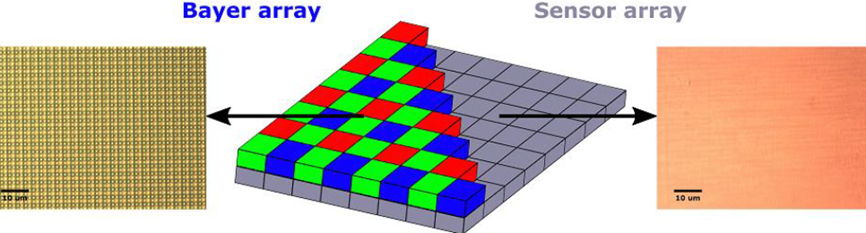
In some cameras, the UV filtration is actually built into the color separation layer (as below), which would likely require significant changes to the signal processing.
Mr. Hunt shared an article with the class about a group that had converted a standard Raspberry Pi camera into an effective UV camera, but with the image processing required to interpret the monochrome signal, they seem to be limited to using it as a still camera. Nonetheless, the success of this paper’s authors would seem to indicate that creating a UV sensitive video camera inexpensively is possible, perhaps by simply removing the UV filter(s) wherever they might be, and then telling the signal processor that it is interpreting a monochrome image.
Problems with the Multi-Camera Adapter
The project would be much easier with monovision, but the stereo vision is much more immersive. Using a multi-camera adapter would make this project simpler, and would also have the advantage that two sets of cameras could be used, e.g. one set for Visible/IR, and another for UV.
Another desired feature Mr. Hunt challenged us to achieve in this setup is to extend the immersive experience to audiences both for educational purposes and for showcasing this project and other school research projects hopefully enabled by this technology, which will require us to be able to record video.
To make the project cool, useful, and at the same time affordable, a Raspberry Pi will be used as the processing unit of the stereo video feed, so the questions we have considered include how to use multiple cameras on a Raspberry Pi. We did find several multiplexing camera adapters, including one from Arducam, that supposedly could support up to four cameras, but since it could only display one image at a time we figured out that the frame-rate would probably be too slow to make it feel like smooth video. In addition, this solution would have made synchronizing and recording very challenging.
The Problem Solver: Synchronized Dual Camera (Arducam SDC)
After Arducam announced the release of their synchronized stereo camera HAT, Mr. Hunt reached out to ask for the product availability. This new product is a HAT-style card on which two Pi cameras can be connected and then forwarded to the Pi’s camera slot. It’s a real stereo adapter with two fully synchronized cameras. What’s interesting about this module is that it incorporates the proprietary ArduChip solution, which tricks the Raspberry Pi into believing that only a single camera is connected to the camera port, so you can really see video feeds from two cameras at the same time.
Our class decided that the SDC board looks like a promising way to solve the stereo display challenges we’re anticipating. We should be able to use it with the Raspberry Pi to capture and process the stereo vision, leaving us only with the issues of how to build UV viewing capabilities into the goggles… it might be simpler to have separate UV sensitive cameras mounted in tandem on the front of the goggles. The upside of this would be that we probably wouldn’t have to engineer a separate filter-changing mechanism since we could use the built-in filter switching ability of un-modified NoIR cameras, and simply optimize the UV cameras for whatever bands we choose. The only issue that would remain would then be switching back and forth between UV and IR modes, hopefully without having to disconnect one set of cameras and reconnect the other.
Building the Enhanced Vision Goggle Project
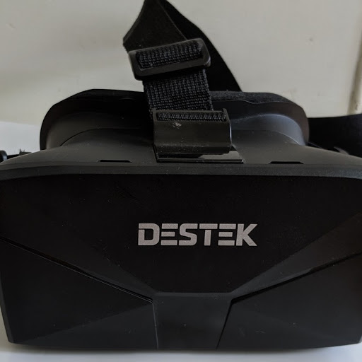
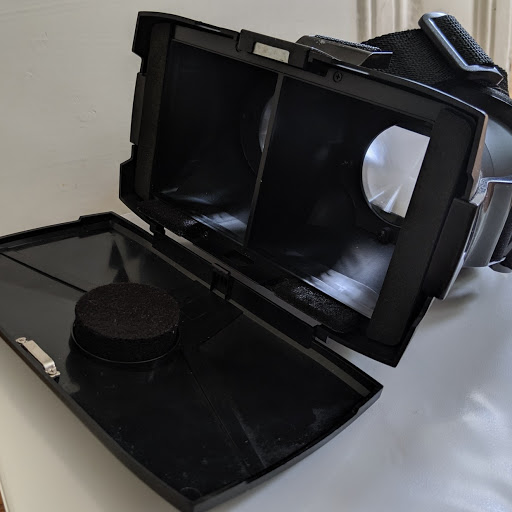
Our class is planning to use a cheap “VR headset” (like the one below – designed to hold a smart-phone) as the chassis for our prototype. On the front (left image) we’ll mount two cameras with lenses centered about pupil-distance apart. The ribbons from these cameras will be threaded through the front cover to the SDC/Raspberry pi assembly, which will be attached to the inside of the front cover. Just behind that assembly will be the LCD monitor, which will sit centered and flush against the divider between the two eyes’ viewing areas (the thin plastic barrier separating the volume in half, visible in the right image)
Also, on the front cover will be mounted multiple IR and UV LEDs for illumination. If we have to use separate cameras for the UV mode, there is enough space on the front cover to accommodate two cameras stacked vertically.
Power will be supplied through a rechargeable LiPO pack that will be worn on a belt to keep the weight of the headset to a minimum.
Our class will continue to work out how to change modes, send operating commands, and adjust programming once we get started working with all the separate components.
About Geoff Hunt :
This post is from Geoff Hunt’s team. Mr.Hunt has two roles at the school – teaching physics and Associate Director of their i2 Program (shorthand for “Inquiry and Innovation”), which is a STEM-focused program for the top performers in each class. He is helping one of the students with a maker-project he’s doing. The goal is to make enhanced vision goggles (like Jordy LaForge from Star Trek had) to enable IR and UV enhanced vision.

