
The Future of Machine Learning Is Tiny
The future of machine learning is tiny.Tweet
From Pete Warden, technical lead of the mobile and embedded TensorFlow group in Google’s Brain team.
Machine learning, seen as a part of artificial intelligence, is the study of computer algorithms that improve automatically through experience.
Tiny machine learning (tinyML) is the intersection of machine learning and embedded internet of things (IoT) devices. The field has the potential to revolutionize many industries.
Before we start, here is a brief introduction to this emerging field from HarvardX.
Tensorflow Lite Micro (tflmicro)
TensorFlow Lite for Microcontrollers is designed to run machine learning models on microcontrollers and other devices with only a few kilobytes of memory.
It supports microcontroller platforms like Arduino Nano 33 BLE Sense, ESP32, STM32F746 Discovery kit, and so on. Since the release of the $4 Raspberry Pi Pico, which has gained increasing popularity among makers, Arducam has been trying to bring what’s possible on other microcontroller platforms to Pico.
- The Future of Machine Learning Is Tiny
- Tensorflow Lite Micro (tflmicro)
- Getting started with Machine Learning with Pico
- Quick Pico Setup
- Person Detection
- Learn More
Getting started with Machine Learning with Pico
This article is a tutorial on using the machine learning framework Tensorflow Lite Micro on the Pico for Person Detection. If you are more interested in the camera part, check out our Raspberry Pi Pico Camera series.
Demo 1: Person Detection on RPi Pico
Demo 2: Person Detection on Arducam Pico4ML
Demo 3: Magic Wand w/ Pico4ML
Demo 4: Wake-Word Recognition w/ Pico4ML
Demo 5: Arducam HM01B0 Camera for Raspberry Pi Pico
Components and Supplies
Complete All-in-One Pico Person Detection Bundle

Tiny Machine Learning Person Detection Bundle for Raspberry Pi Pico
$39.99
Available now: Pico4ML, one dev board for all Tensorflow Light Micro Examples
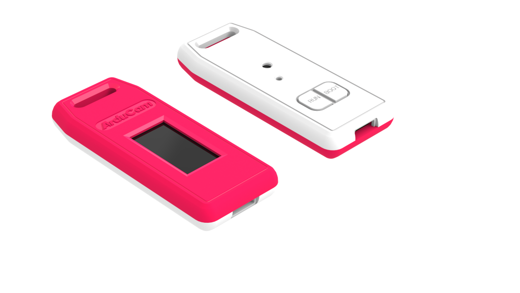
RP2040 Dev Board w/ QVGA Camera, Microphone, LCD & More
Components of Pico person detection project
| 1 × Arducam Mini 2MP Plus | UCTRONICS | Amazon |
| 1 × Raspberry Pi Pico | RPi | Amazon |
| 1 × USB to TTL Converter | Amazon |
| Jumper Wires | Amazon |
| 1 × Micro USB cable | Amazon |
See Getting Started with the Raspberry Pi Pico and the README in the pico-sdk for information on getting up and running.
Quick Pico Setup
If you are developing for Raspberry Pi Pico on Raspberry Pi 4B, or the Raspberry Pi 400, most of the installation steps in this Getting Started guide can be skipped by running the setup script. You can get this script by doing the following:
git clone https://github.com/raspberrypi/pico-setup.gitThen run:
pico-setup/pico_setup.shThe script will:
- Create a directory called pico
- Install required dependencies
- Download the pico-sdk, pico-examples, pico-extras, and pico-playground repositories
- Define PICO_SDK_PATH, PICO_EXAMPLES_PATH, PICO_EXTRAS_PATH, and PICO_PLAYGROUND_PATH in your ~/.bashrc
- Build the blink and hello_world examples in pico-examples/build/blink and pico-examples/build/hello_world
- Download and build picotool (see Appendix B). Copy it to /usr/local/bin. • Download and build picoprobe (see Appendix A).
- Download and compile OpenOCD (for debug support)
- Download and install Visual Studio Code
- Install the required Visual Studio Code extensions (see Chapter 6 for more details)
- Configure the Raspberry Pi UART for use with Raspberry Pi Pico
Once it has run, you will need to reboot your Raspberry Pi,
sudo rebootPerson Detection
Person Detection Diagram

- Download RPI-Pico-Cam
git clone https://github.com/ArduCAM/RPI-Pico-Cam.git- Compile
Tip
If you don’t want to compile, use the pre-built uf2 file below , you only need to wire the hardware and download uf2 to the device.
cd RPI-Pico-Cam/tflmicro
mkdir build
cd build
cmake ..
make
Then you will create some files under RPI-Pico-Cam/tflmicro/build/examples/person_detection path
| Bin | Description |
|---|---|
| person_detection_int8.uf2 | This is the main program of person_detection, which can be dragged onto the RP2040 USB Mass Storage Device. |
| person_detection_benchmark.uf2 | This is the benchmark program of person_detection, you can use it to test the performance of person_detection on pico. |
| image_provider_benchmark.uf2 | This is the benchmark program of image_provider, you can use it to test the performance of image data acquisition. |

Test Person Detection
| App | Description |
|---|---|
| person_detection_int8 | This is a person detection demo. |
- Hardware connection

- Load and run person_detection The simplest method to load software onto a RP2040-based board is by mounting it as a USB Mass Storage Device. Doing this allows you to drag a file onto the board to program the flash. Go ahead and connect the Raspberry Pi Pico to your Raspberry Pi using a micro-USB cable, making sure that you hold down the BOOTSEL button to force it into USB Mass Storage Mode.
If you are logged in via ssh for example, you may have to mount the mass storage device manually:
$ dmesg | tail
[ 371.973555] sd 0:0:0:0: [sda] Attached SCSI removable disk
$ sudo mkdir -p /mnt/pico
$ sudo mount /dev/sda1 /mnt/pico
If you can see the files in /mnt/pico then the USB Mass Storage Device has been mounted correctly:
$ ls /mnt/pico/
INDEX.HTM INFO_UF2.TXT
Copy your person_detection_int8.uf2 onto RP2040:
sudo cp examples/person_detection/person_detection_int8.uf2 /mnt/pico
sudo sync
View output
The person detection example outputs some information through usb, you can use minicom to view:
minicom -b 115200 -o -D /dev/ttyACM0
This person detection example also outputs image data and person detection results to the UART, and we provide a processing program to display them:
Tip:
You can download the Processing here or Processing for Pi.


Learn More
- The TensorFlow website has information on training, tutorials, and other resources.
- The TinyML Book is a guide to using TensorFlow Lite Micro across a variety of different systems.
- TensorFlowLite Micro: Embedded Machine Learning on TinyML Systems has more details on the design and implementation of the framework.
- Visit, star, or fork Arducam Pico Cam GitHub Repo.
What’s your take on this? Leave your comments below!


Thanks for sharing this! I was thinking about something similar, and now that you’ve proved that it can be done, I’ll try it as soon as my Pico arrives.
Why do you need another usb plug. Cant you get the same thing through the on board usb?
With the on-board USB connector, the Pico will be identified as a
ttyACM0device rather thanttyUSB. Our Windows PC recognizes thettyACM0, but it can’t send or receive data. Since we’re unable to figure out what the reason is while we were making this tutorial, we had to find another way to communicate to the PC. Using the real serial port on board and a USB-TTL adapter becomes our solution.This looks really wonderful. I’ve tried it on my brand new Pico though, and for some reason it says it “Can’t find ov2640 sensor”.
I don’t have a USB to TTL converter connected, but that shouldn’t affect it. To ensure that communication over the main USB port does not affect anything, I have adjusted the code of the Arducam demo to indicate camera connectivity with the on-board LED, and alas, it fails.
I have tried with 2 cameras, in case the first one was faulty, and it fails with both.
I have also tried both a local build as well as the pre-built uf2 from here, with the same result.
Any input on what else to try would be highly appreciated!
Generally speaking, “can’t find ov2640 sensor” results from wiring issues, especially I2C or power ones. However, in this case, we have to use a USB-TTL converter because with the main USB port connected, the Pico is identified as a
ttyACM0device and our Windows PC just won’t talk to it, and we had to use the USB-TTL to set up communication while we made this demo.What cameras are supported other than the one mentioned in the article? Apologies for my personal comprehension skills in not digesting this specific information if it has been detailed in the article. Thanks.
Kind regards.
Re “can’t find ov2640 sensor” resulting from wiring issues, after revisiting this, I’ve noticed that the wiring diagram in this article seems to have gotten the pin numbering wrong for the SCL pin.
In the image, the camera’s SCL pin is connected to the Pico’s pin 10, which is GP7, whereas it should be connected to pin 12, which is GP9.
I initially went by the image blindly, rather than the table. After working from the table and a pinout map I located the problem, moved the SCL to GP9, and now it works like a charm.
Can I connect the OV7675 camera to a Raspberry Pi and capture images or video that way? if so, what’s a good resource? I’m new to the Raspberry Pi.