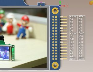
Pin definition:
| Signals | Description | Signals | Description |
| +3.3V | +3.3V from shield | +5V | +5V from Arduino |
| D1 | 3.3V logic version of D1 | D0 | 3.3V logic version of D0 |
| D3 | 3.3V logic version of D3 | D2 | 3.3V logic version of D2 |
| D5 | 3.3V logic version of D5 | D4 | 3.3V logic version of D4 |
| D7 | 3.3V logic version of D7 | D6 | 3.3V logic version of D6 |
| D9 | 3.3V logic version of D9 | D8 | 3.3V logic version of D8 |
| +3.3V | +3.3V from shield | GND | Ground |
| IO1 | Expansion GPIO1 | IO0 | Expansion GPIO0 |
| D11 | 3.3V logic version of D11 | D13 | 3.3V logic version of D13 |
| IO2 | Expansion GPIO2 | D12 | 3.3V logic version of D12 |
| IO3 | Expansion GPIO3 | D10 | 3.3V logic version of D10 |
| IO5 | Expansion GPIO5 | IO4 | Expansion GPIO4 |
| A0 | 3.3V logic version of A0 | A1 | 3.3V logic version of A1 |
| A2 | 3.3V logic version of A2 | A3 | 3.3V logic version of A3 |
| A4 | 3.3V logic version of A4 | A5 | 3.3V logic version of A5 |
| GND | Ground | GND | Ground |
Arduino board use IOs to emulate parallel bus to access ArduChip internal registers and external LCD registers. User should instantiate the ArduCAM and UTFT class which use parallel bus before the setup routine. The function of each signal list as follows:
| Signals | Functions |
| D[7:0] | Parallel bus data[7:0] |
| A0 | Parallel bus RD, active low |
| A1 | Parallel bus WR, active low |
| A2 | Parallel bus RS |
| A3 | Parallel bus CS, active low |
| A4 | I2CSDA for Camera Module |
| A5 | I2CSCL for Camera Module |
| D10 | LCD chipselect, active low |
| D9 | SD/TF chipselect, active low |
| D11 | SPI MOSI |
| D12 | SPI MISO |
| D13 | SPI SCLK |
The following is a piece of the code for demonstration of the instantiate the ArduCAM and UTFT class.
#define SD_CS 9

//UTFT(byte model, int RS, int WR, int RD, int CS)
UTFT myGLCD(ITDB32S,A2,A1,A0,10);
//ArduCAM(byte model,int RS, int WR, int RD, int CS)
ArduCAM myCAM(OV7670,A2,A1,A0,A3);

void setup()
{
  // Setup I2C port
  Wire.begin();
  if (!SD.begin(SD_CS))
  {
    while (1);
  }
  // Setup ArduChip
  myCAM.InitCAM();
  // Setup the LCD
  myGLCD.InitLCD();
  ShowStart();
  delay(2000);
}

