Simplifying Embedded Vision, Innovation Made Easy.
Embedded vision is often seen as a complex and challenging field, requiring specialized expertise and resources. Arducam offers a selected range of innovative, user-friendly and cost-effective solutions to simplify the process of integrating vision capabilities into embedded systems, enabling innovators to focus on their ideas and bring them to life more easily and quickly.
Lens Selection Guide
Camera Selection Guide
About Us
A leading provider of embedded vision solutions, serving over 2,000 commercial clients since 2012.
We offer cutting-edge camera modules, accessories, and software tools for businesses in a range of industries, including robotics, automotive, healthcare, agriculture, and more.
Our products are designed to be reliable, scalable, and cost-effective, and can be customized to meet the specific needs of our clients. At ArduCam, we’re dedicated to providing our clients with the tools and resources they need to succeed and pushing the boundaries of what’s possible in embedded vision.
Whether you’re a startup, growing business, or established enterprise, ArduCam is here to help you harness the power of embedded vision.
Core TecHNOLOGY

Flexible ISP Technology
Arducam’s proprietary image processing engine allows us to tune camera module parameters and sensor settings to meet the specific requirements of our clients’ applications. With our flexible ISP technology, we can seamlessly integrate a wide range of image sensors, with no restriction by the ISP level of the embedded platform, ensuring maximum image quality and versatility.

Highly Abstracted Embedded Camera Architecture
Our unified control interface provides a standardized way to access and control Arducam modules, making it easy to upgrade and maintain software and drivers. By abstracting the sensor parameters, we ensure consistent performance across all of our camera modules, regardless of the sensor vendor.

Advanced Embedded Image Sensor Packaging Technology
We have extensive experience in designing and manufacturing complex embedded camera modules using Chip on Board (COB), System in Package (SiP) and Land Grid Array (LGA), and other advanced packaging technologies. Our state-of-the-art production facilities allow us to deliver high-quality camera modules that meet the unique requirements of even the most demanding applications.
SOLUTIONS
At Arducam, we not only offer selected off-the-shelf products but also actively deliver a diversity of solutions to help you achieve success in your project goals. They may come in the form of a package of items, a tool kit, or a tailored customized service to help ensure the success of your project.

Flexible-ISP Solution
Adjust relevant parameters to support various image sensors, meeting diverse user needs with no restriction by the ISP level of the embedded platform.

Quick Camera Evaluation
Help users quickly evaluate Arducam camera modules, reducing development time and cost.

Multi-camera Solution
An integrated multi-camera solution with synchronized multiple cameras, ideal for applications such as 3D scanning and stereo vision.

Camera Cable Extension
Extend the distance between the camera module and the processor board, solving the distance limitation problem.

Edge AI Solution
Arducam works with third-party partners to provide Edge AI solutions, enabling smart analysis and decision-making on embedded devices.

Sensor Packaging
Custom-designed packaging for image sensors, providing a complete end-to-end solution to satisfy different application scenarios.
Products
Arducam provides a wide range of selected embedded vision products to support the success of your projects.
Selected from a variety of standard off-the-shelf items
User-friendly and super easy for your quick evaluation
Compatible with all major embedded open-source platforms
Supports multiple interfaces for increased versatility
Offers both high-end and low-end products to suit different needs
Make your development process simpler.
-1522.png "1522")
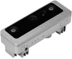
Evaluation Kit (EVK)
Accelerate your Proof of Concept process and reduce the development time from months to days by our pre-engineered USB camera.
-2.png)
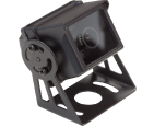
Embedded Camera Module
Designed for seamless integration into Arduino, Raspberry Pi, NVIDIA Jetson, Rockchip, NXP, Renesas, etc.
UVC Camera Module
Plug-n-play USB cameras fitting all platforms, supporting video conferencing, live streaming, machine vision, and more.
Edge AI
TinyML on MCU, Context-based video analytics, 3D Depth AI, and many more Edge AI devices with Arducam machine vision inside.
-4-1.png)
Optical Components
Lenses, filters, image sensors, lens holders, and other essential optical elements made by a selected network of top-level suppliers.
Over one million pcs/sets of Arducam branded products will be delivered worldwide annually.
Over 10000 individual & orgnizational users of Arducam solutions.
Arducam solutions available in over 100 countries/areas globally.
Over 60 trusted distributors & agents all over the world.
PARTNERS/COLLABORATORS
Teamwork delivers value best.
We are proud to be a trusted partner with big names in the industry. We value our potential partnerships with various types of embedded vision hardware users, hardware manufacturers, software companies, system integrators, research institutions, universities, resellers and distributors, healthcare and medical devices, transportation, energy and utilities, education and research, environmental monitoring, aerospace and defence, robotics, industrial automation, gaming and entertainment, smart home device, security and surveillance, retail and hospitality, agricultural technology, etc.


CUSTOMIZATION SERVICE
We understand that every organization has unique needs and challenges that cannot always be addressed by off-the-shelf products or solutions. That’s why we offer a comprehensive customization service to meet your specific requirements. If you can’t find a ready-made product or solution that fits your needs, we welcome you to work with us to develop a tailored solution that meets your exact specifications. We will try our best to help you. Contact us today to discuss your custom camera module needs.
