
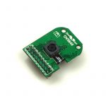
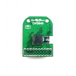
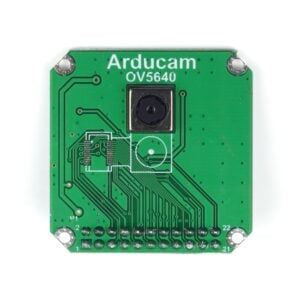
ArduCAM now released a new 5MegaPixel AutoFocus CMOS camera module with JPEG output. The camera module is based on Omnivision OV5640 image sensor and can be used with ArduCAM shields and other platforms like Freescale i.MX6 develop board.
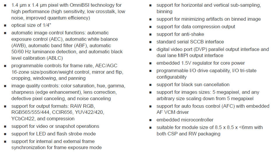
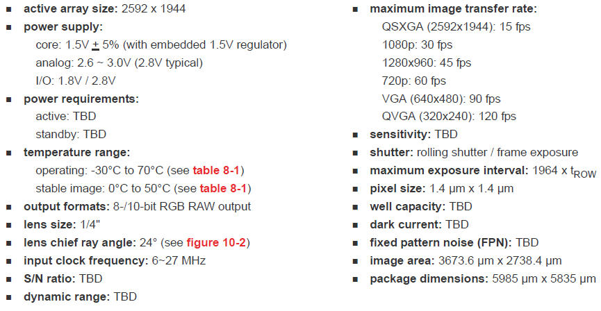
The OV5640 (color) image sensor is a low voltage, high-performance, 1/4-inch 5 megapixel CMOS image sensor that provides the full functionality of a single chip 5 megapixel (2592×1944) camera using OmniBSI™ technology in a small footprint package. It provides full-frame, sub-sampled, windowed or arbitrarily scaled 8-bit/10-bit images in various formats via the control of the Serial Camera Control Bus (SCCB) interface.
The OV5640 has an image array capable of operating at up to 15 frames per second (fps) in 5 megapixel resolution with complete user control over image quality, formatting and output data transfer. All required image processing functions, including exposure control, gamma, white balance, color saturation, hue control, defective pixel canceling, noise canceling, etc., are programmable through the SCCB interface or embedded microcontroller. The OV5640 also includes a compression engine for increased processing power. In addition, Omnivision image sensors use proprietary sensor technology to improve image quality by reducing or eliminating common lighting/electrical sources of image contamination, such as fixed pattern noise, smearing, etc., to produce a clean, fully stable, color image.
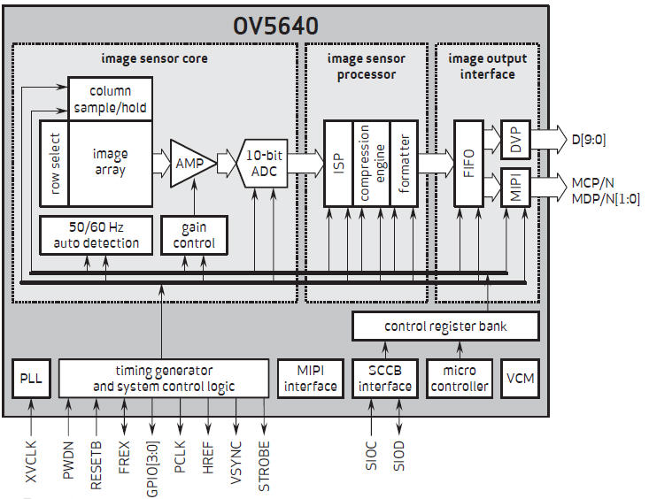
The OV5640 module uses standard ArduCAM camera pin out. And the OV5640 support both DVP (parallel) and MIPI interface with some shared pins. User can configure the module with different interface mode and pin out definition is list as follows.
DVP interface
| Pin No. | PIN NAME | TYPE | DESCRIPTION |
| 1 | VCC | POWER | 3.3v Power supply |
| 2 | GND | Ground | Power ground |
| 3 | SCL | Input | Two-Wire Serial Interface Clock |
| 4 | SDATA | Bi-directional | Two-Wire Serial Interface Data I/O |
| 5 | VSYNC | Output | Active High: Frame Valid; indicates active frame |
| 6 | HREF | Output | Active High: Line/Data Valid; indicates active pixels |
| 7 | PCLK | Output | Pixel Clock output from sensor |
| 8 | XCLK | Input | Master Clock into Sensor |
| 9 | DOUT9 | Output | Pixel Data Output 9 (MSB) |
| 10 | DOUT8 | Output | Pixel Data Output 8 |
| 11 | DOUT7 | Output | Pixel Data Output 7 |
| 12 | DOUT6 | Output | Pixel Data Output 6 |
| 13 | DOUT5 | Output | Pixel Data Output 5 |
| 14 | DOUT4 | Output | Pixel Data Output 4 |
| 15 | DOUT3 | Output | Pixel Data Output 3 |
| 16 | DOUT2 | Output | Pixel Data Output 2 (LSB) |
| 17 | M+ | POWER | Power for VCM |
| 18 | GND | Ground | Ground for VCM |
| 19 | RST | Input | Sensor reset signal, active low |
| 20 | PWDN | Input | Power down input, active high |
MIPI interface
| Pin No. | PIN NAME | TYPE | DESCRIPTION |
| 1 | VCC | POWER | 3.3v Power supply |
| 2 | GND | Ground | Power ground |
| 3 | SCL | Input | Two-Wire Serial Interface Clock |
| 4 | SDATA | Bi-directional | Two-Wire Serial Interface Data I/O |
| 5 | VSYNC | Output | NA |
| 6 | HREF | Output | NA |
| 7 | PCLK | Output | NA |
| 8 | XCLK | Input | Master Clock into Sensor |
| 9 | DOUT9 | Output | MIPI port MDP1 |
| 10 | DOUT8 | Output | MIPI port MDN1 |
| 11 | DOUT7 | Output | MIPI port MCP |
| 12 | DOUT6 | Output | MIPI port MCN |
| 13 | DOUT5 | Output | MIPI port MDP0 |
| 14 | DOUT4 | Output | MIPI port MDN0 |
| 15 | DOUT3 | Output | NA |
| 16 | DOUT2 | Output | NA |
| 17 | M+ | POWER | Power for VCM |
| 18 | GND | Ground | Ground for VCM |
| 19 | RST | Input | Sensor reset signal, active low |
| 20 | PWDN | Input | Power down input, active high |
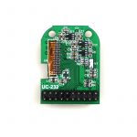
USB 3.0 Interface
USB 3.0 quick development and evaluation board for sensors like OV5640.
- Demonstration
ArduCAM provides a full demonstration for OV5640 camera module on Arduino platform. Please download the ArduCAM_Shield_V2_Camera_Playback.ino from github.
It will turn the ArduCAM into a real digital camera with capture and playback functions.
1. Preview the live video on LCD Screen.
2. Capture and buffer the image to FIFO when shutter pressed quickly.
3. Store the image to Micro SD/TF card with BMP format.
4. Playback the capture photos one by one when shutter button hold on for 3 seconds.
This program requires the latest ArduCAM library and ArduCAM Shield_V2 ArduCAM shield and use Arduino IDE 1.6.8 compiler or above.

