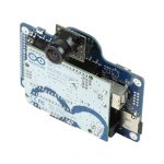
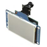
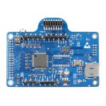
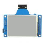
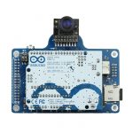
This camera shield is replaced by newer Rev.C+ shield and ArduCAM-Mini board
ArduCAM is Arduino based open source camera platform which is well mated to Arduino boards. It now supports Arduino UNO board and we will add support Mega1280/2560 and new released Leonardo, Maple and Chipkit are also in planning.
Features:
- 3.2 inch TFT LCD Screen 320×240 resolution
- Support various of camera modules
- Support larger than 8GB SD/TF card read and write
- FAT filesystem support
- 320×240 RGB565/RGB555 BMP file format capture and playback
- Trigger in and trigger out events ability
- GPIO expansion support
- Well mated with Arduino board
LCD Module
The TFT LCD is 3.2 inch QVGA ( 320×240 ) LCD, it use SSD1289 LCD controller and consists of up to 172,800 bytes (240 x 320 x 18 / 8) Graphic Display Data RAM (GDDRAM). It interfaces to Arduino with 8bit 8080 type bus interface. It is good to know that Henning Karlsen has already develop a open source library named UTFT for Arudino, it also support this LCD controller.
Camera Module
We will add support (already supported sensors are marked in red) to various of camera module which use Omnivision and Aptina CMOS image sensor, something like
- 0.3 Mega Pixel : OV7660, OV7670, OV7675, OV7725
- 1.3 Mega Pixel : OV9650, OV9655, MT9M111, MT9M112, MT9M001
- 2 Mega Pixel : OV2640, MT9D111, MT9D112
- 3 Mega Pixel : OV3640, MT9T112
- 5 Mega Pixel : OV5640, OV5642, MT9P111
MCU Platform
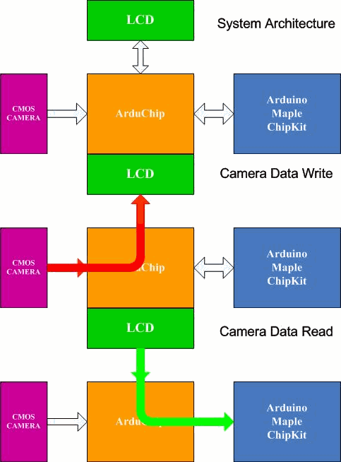
Two libraries are written for ArduCAM shield, one is UTFT library which is used for accessing the LCD screen, the other is ArduCAM library which supports different kind of camera modules registers configuration via I2C and accessing ArduChip internal control registers. ArduCAM library provide simple interface for sensor initialization, triggering a capture and read image data to external SD/TF card.
ArduChip
ArduCAM incorporate with a ArduChip, which used to do the DMA transfer between camera module and LCD internal GDDRAM, control the camera data stream timing and do the GPIO expansion. When start the state machine will enter preview mode, the Chip DMA the camera data to LCD screen directly with frame rate upto 30fps. Once the capture button is pressed, the state machine will freeze the screen and enter capture mode, the MCU will read the image data from LCD’s GDDRAM and save to SD/TF card.
Limitations ( The limitation is improved in the ArduCAM Rev.B and Rev.C)
We can’t live without the LCD screen because we use the LCD GRAM as a frame buffer. The image resolution is limited by the LCD screen, so it only supports QVGA(320×240) preview resolution or equivalent 150KB size (around SXGA 1280×1024) JPEG image. It is OK for machine vision and small applications.
Due to the speed limitation of AVR series MCU, and all the Read and Write access to LCD GRAM is emulated by IO operation, saving a 320×240 RGB555 BMP into SD/TF card will take up 10 seconds and transmit the image over bluetooth needs 15 seconds. It is OK for the demostration, but I do think it will be resolved when we move to more powerful MCU platform like Maple and Chipkit.


