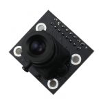
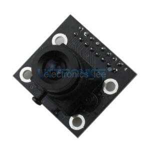
The Aptina® Imaging MT9V111 is a 1/4-inch VGA-format CMOS active-pixel digital image sensor, the result of combining the MT9V011 image sensor core with Micron Imaging’s third-generation digital image flow processor technology. The MT9V111 has an active imaging pixel array of 649 x 489, capturing high-quality color images at VGA resolution. The sensor is a complete camera-on-a-chip solution and is designed specifically to meet the demands of battery-powered products such as cellular phones, PDAs, and toys. It incorporates sophisticated camera functions on-chip and is programmable through a simple two-wire serial interface.
- Features
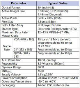
- Optical size 1/4 inch
- Resolution 640×480 VGA
- Onboard regulator, only single 3.3V supply needed
- Standard 0.1inch (54mm) pin pitch header connector
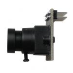
- Mounted with high quality F1.8 / 6mm lens
- Ultra low-power, low cost CMOS image sensor Superior low-light performance
- Up to 30 fps progressive scan at 27 MHz for high quality video at VGA resolution
- On-chip Image Flow Processor (IFP) performs sophisticated processing: color recovery and correction, sharpening, gamma, lens shading correction, on-the-fly defect correction, 2X fixed zoom
- Image decimation to arbitrary size with smooth, continuous zoom and pan
- Automatic exposure, white balance and black compensation, flicker avoidance, color saturation, and defect identification and correction, auto frame rate, back light compensation
- Two-wire serial programming interface
- ITU_R BT.656 (YCbCr), YUV, 565RGB, 555RGB, and 444RGB output data formats
- Application
- Cellular phones
- PDAs
- Toys
- Other battery-powered products
- Can be used in Arduino, Maple, ChipKit, STM32, ARM, DSP, FPGA platforms
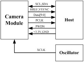
The following schematic diagram show a basic camera based system. The camera module is powered from a single +3.3V power supply. An external oscillator provide the clock source for camera module XCLK pin. With proper configuration to the camera internal registers via I2C bus, then the camera supply pixel clock (PCLK) and camera data (Data[9:0]) back to the host with synchronize signal like HREF and VSYNC.
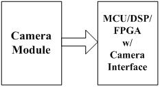
The host may have integrate camera interface like STM32F2 or STM32F4 series MCUs, or ARM9/11 which has dedicate camera port, and DPS like TI TMS320DM series, as well as FPGAs that user can design special logic for camera application. The typical connection between these system and camera module would show like following diagram.
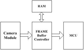
For the host that doesn’t have a dedicate camera interface, additional hardware is needed. User need to buffer a entire frame before read them out with low speed MCUs. For example ArduCAM shield is a additional hardware that can be connected to Arduino UNO/Mega board, user can take a photo or something like that easily. The following diagram show the system without dedicate camera interface.
| Pin No. | PIN NAME | TYPE | DESCRIPTION |
| 1 | VCC | POWER | 3.3v Power supply |
| 2 | GND | Ground | Power ground |
| 3 | SCL | Input | Two-Wire Serial Interface Clock |
| 4 | SDATA | Bi-directional | Two-Wire Serial Interface Data I/O |
| 5 | VSYNC | Output | Active High: Frame Valid; indicates active frame |
| 6 | HSYNC | Output | Active High: Line/Data Valid; indicates active pixels |
| 7 | PCLK | Output | Pixel Clock output from sensor |
| 8 | XCLK | Input | Master Clock into Sensor |
| 9 | DOUT7 | Output | Pixel Data Output 7 (MSB) |
| 10 | DOUT6 | Output | Pixel Data Output 6 |
| 11 | DOUT5 | Output | Pixel Data Output 5 |
| 12 | DOUT4 | Output | Pixel Data Output 4 |
| 13 | DOUT3 | Output | Pixel Data Output 3 |
| 14 | DOUT2 | Output | Pixel Data Output 2 |
| 15 | DOUT1 | Output | Pixel Data Output 1 |
| 16 | DOUT0 | Output | Pixel Data Output 0 (LSB) |
- Demonstration
ArduCAM provides a full demonstration for MT9V111 camera module on Arduino platform. Please download the ArduCAM_Shield_V2_Camera_Playback.inofrom github.
It will turn the ArduCAM into a real digital camera with capture and playback functions.
1. Preview the live video on LCD Screen.
2. Capture and buffer the image to FIFO when shutter pressed quickly.
3. Store the image to Micro SD/TF card with BMP format.
4. Playback the capture photos one by one when shutter button hold on for 3 seconds.
This program requires the latest ArduCAM library and ArduCAM Shield_V2 ArduCAM shield and use Arduino IDE 1.5.2 compiler or above.
