


[Discontinued] Arducam OV7670 0.3 Megapixel Camera Module for Arduino Boards
SKU
B0023
Discontinued, check alternative item B0463.
- This Arduino camera comes with an F1.8/6 mm lens, it also supports AEC, AGC, AWB, ABF and ABLC, detailed specifications can be found below.
- It can be connected to most Arduino boards, although we’d recommend using our SPI Modules for better performances.
- Program requires the latest ArduCAM library and?ArduCAM Shield_V2 shield and use Arduino IDE 1.6.8 compiler or above.
$5.52

Overview
Specifications
Wiki
Documents
Video
Customization
Overview
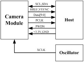
The following schematic diagram show a basic camera based system. The camera module is powered from a single +3.3V power supply. An external oscillator provide the clock source for camera module XCLK pin. With proper configuration to the camera internal registers via I2C bus, then the camera supply pixel clock (PCLK) and camera data (Data[9:0]) back to the host with synchronize signal like HREF and VSYNC.
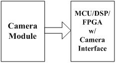
The host may have integrate camera interface like STM32F2 or STM32F4 series MCUs, or ARM9/11 which has dedicate camera port, and DPS like TI TMS320DM series, as well as FPGAs that user can design special logic for camera application. The typical connection between these system and camera module would show like following diagram.
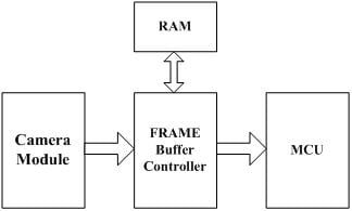
For the host that doesn’t have a dedicate camera interface, additional hardware is needed. User need to buffer a entire frame before read them out with low speed MCUs. For example ArduCAM shield is a additional hardware that can be connected to Arduino UNO/Mega board, user can take a photo or something like that easily. The following diagram show the system without dedicate camera interface.
Applications
- Cellular phones
- PDAs
- Toys
- Other battery-powered products
- Can be used in Arduino, Maple, ChipKit, STM32, ARM, DSP, FPGA platforms
Features & Specs
- Optical size 1/6 inch
- Resolution 640×480 VGA
- Onboard regulator, only single 3.3V supply needed
- Standard 0.1inch (2.54mm) pin pitch header connector
- Mounted with high quality F1.8 / 6mm lens
- Output support for Raw RGB, RGB (GRB 4:2:2, RGB565/555/444), YUV (4:2:2) and YCbCr (4:2:2) formats
- High sensitivity for low-light operation
- Low operating voltage for embedded portable apps
- Standard SCCB interface compatible with I2C interface
- Supports image sizes: VGA, CIF, and any size scaling down from CIF to 40×30
- VarioPixel® method for sub-sampling
- Automatic image control functions including: Automatic Exposure Control (AEC), Automatic Gain Control (AGC), Automatic White Balance (AWB), Automatic
- Band Filter (ABF), and Automatic Black-Level Calibration (ABLC)
- Image quality controls including color saturation, hue, gamma, sharpness (edge enhancement), and anti-blooming
- ISP includes noise reduction and defect correction
- Supports LED and flash strobe mode
- Supports scaling
- Lens shading correction
- Flicker (50/60 Hz) auto detection
- Saturation level auto adjust (UV adjust)
- Edge enhancement level auto adjust
- De-noise level auto adjust
Pin Definition
| Pin No. | PIN NAME | TYPE | DESCRIPTION |
| 1 | VCC | POWER | 3.3v Power supply |
| 2 | GND | Ground | Power ground |
| 3 | SCL | Input | Two-Wire Serial Interface Clock |
| 4 | SDATA | Bi-directional | Two-Wire Serial Interface Data I/O |
| 5 | VSYNC | Output | Active High: Frame Valid; indicates active frame |
| 6 | HREF | Output | Active High: Line/Data Valid; indicates active pixels |
| 7 | PCLK | Output | Pixel Clock output from sensor |
| 8 | XCLK | Input | Master Clock into Sensor |
| 9 | DOUT9 | Output | Pixel Data Output 9 (MSB) |
| 10 | DOUT8 | Output | Pixel Data Output 8 |
| 11 | DOUT7 | Output | Pixel Data Output 7 |
| 12 | DOUT6 | Output | Pixel Data Output 6 |
| 13 | DOUT5 | Output | Pixel Data Output 5 |
| 14 | DOUT4 | Output | Pixel Data Output 4 |
| 15 | DOUT3 | Output | Pixel Data Output 3 |
| 16 | DOUT2 | Output | Pixel Data Output 2 (LSB) |
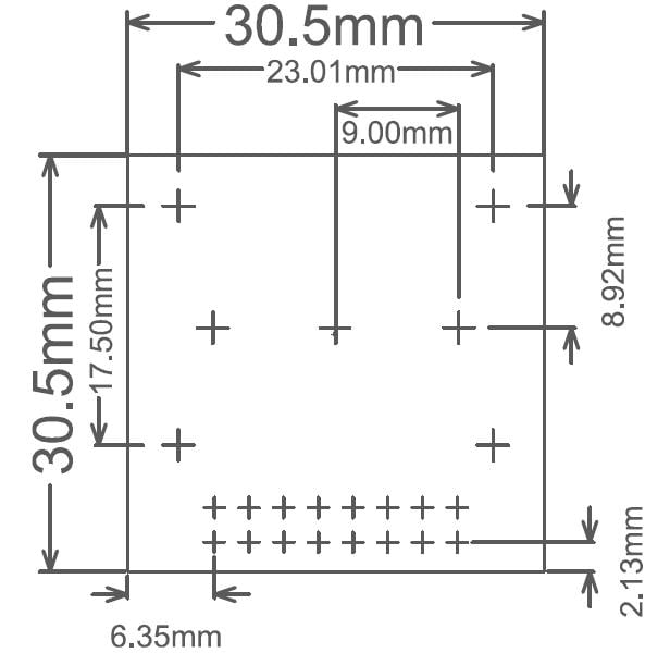
Mechanical Dimension
Demonstration
ArduCAM provides a full demonstration for OV7670 camera module on Arduino platform. Please download the ArduCAM_Shield_V2_Camera_Playback.ino from github.
It will turn the ArduCAM into a real digital camera with capture and playback functions.
1. Preview the live video on LCD Screen.
2. Capture and buffer the image to FIFO when shutter pressed quickly.
3. Store the image to Micro SD/TF card with BMP format.
4. Playback the capture photos one by one when shutter button hold on for 3 seconds.
Datasheet
Arducam_ov7670_cmos_camera_module_revc_ds
Documentation
Introduction
The Arducam team invented the world’s first high resolution SPI camera solution for Arduino in 2012. Since then, the ArduCam SPI cameras fill the gaps missing in the Arduino camera community. These SPI cameras are general-purpose solutions, not limited to the Arduino platform, but can be used on any hardware platforms that have the SPI […]
Customization
About Arducam's Customization Services:
If off-the-shelf solutions don't meet your needs, Arducam offers end-to-end custom camera design services to help you turn your ideas into real products. From early concept to mass production, we work closely with you to tailor an imaging solution to meet your unique technical requirements and product goals.
What can Arducam customize?
Sensor/Lens/circuit/interface;
Optical filter/housing/ISP, and more.
For more information about Arducam's custom design, please refer to: Arducam Custom Design