


![[Discontinued] Arducam NoIR IMX219-AF Programmable/Auto Focus IR Sensitive Camera Module for NVIDIA Jetson Nano/Xavier NX](https://www.arducam.com/media/catalog/product/cache/2efa09db93707dc55d4d0c42c50c0492/a/r/arducam_8mp_autofocus_jetsonnano_b0181_2-1.jpg)
![[Discontinued] Arducam 2MP OV2640 Color 1/4” Camera Module with LS-4011 M12 Mount lens](https://www.arducam.com/media/catalog/product/cache/2efa09db93707dc55d4d0c42c50c0492/a/r/arducam-breakout-board-2mp-ov2640-m12-color-u3359-0.jpg)
Arducam 2MP OV2640 1/4” Camera Breakout Board
SKU
OV2640
Recommending Reading: OV2640 Full Report – Specs, Cameras, Features, and Alternatives
- We also have the OV2640 SPI module if you want to use this on Arduino UNO boards, MCU, ARM, DSP and FPGA platforms.
- M12/CS mount lens holder with changeable lens options.
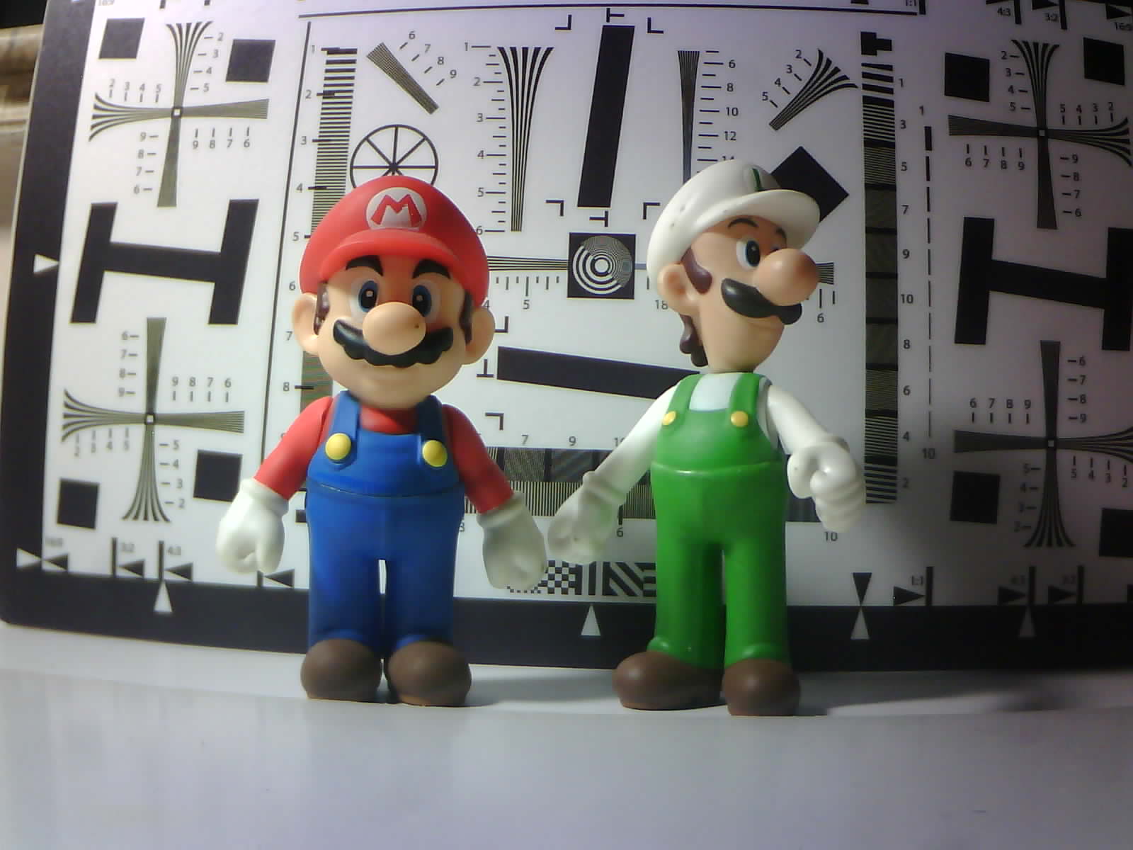
- Decent low light performance (details can be found below).
- Low power consumption
$1.00
Overview
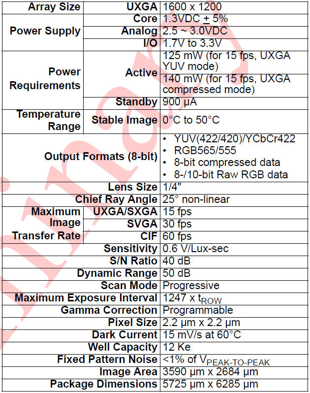
Specifications
Wiki
Documents
Video
Customization
OV2640 – Specs, Datasheets, Cameras, Features, Alternatives
OV2640, an evergreen image sensor from OmniVision. It was released in 2005 and discontinued in 2009, yet still used a lot in today’s products. While this image sensor remains popular, there are also uncertainties ahead. You may have questions like the followings: What’s good about it? What makes it so popular? How to deal with […]
Overview
Application
- Cellular phones
- PDAs
- Toys
- Other battery-powered products
- Can be used in MCU, Raspberry Pi, ARM, DSP, FPGA platforms
Features
- Flex type module or M12 mount lens holder with more lens options module
- 1/4” sensor size
- High sensitivity for low-light operation
- Standard SCCB interface
- Output support for Raw RGB, RGB (RGB565/555), GRB422, YUV (422/420) and YCbCr (4:2:2) formats, JPEG compression formats
- Supports image sizes: UXGA, SXGA, SVGA, and any size scaling down from SXGA to 40×30
- Automatic image control functions including Automatic Exposure Control (AEC), Automatic Gain Control (AGC), Automatic White Balance (AWB), Automatic Band Filter (ABF), and Automatic Black-Level Calibration (ABLC)
- Image quality controls including color saturation, gamma, sharpness (edge enhancement), lens correction, white pixel canceling, noise-canceling, and 50/60 Hz luminance detection
- Low operating voltage for embedded portable apps
Specifications
Datasheets
- OV2640 Camera User Guide
- OminiVision OV2640 Sensor Datasheet
Pin Definition
| Pin No. | PIN NAME | TYPE | DESCRIPTION |
| 1 | VCC | POWER | 3.3v Power supply |
| 2 | GND | Ground | Power ground |
| 3 | SCL | Input | Two-Wire Serial Interface Clock |
| 4 | SDATA | Bi-directional | Two-Wire Serial Interface Data I/O |
| 5 | VSYNC | Output | Active High: Frame Valid; indicates active frame |
| 6 | HREF | Output | Active High: Line/Data Valid; indicates active pixels |
| 7 | PCLK | Output | Pixel Clock output from the sensor |
| 8 | XCLK | Input | Master Clock into Sensor |
| 9 | DOUT9 | Output | Pixel Data Output 9 (MSB) |
| 10 | DOUT8 | Output | Pixel Data Output 8 |
| 11 | DOUT7 | Output | Pixel Data Output 7 |
| 12 | DOUT6 | Output | Pixel Data Output 6 |
| 13 | DOUT5 | Output | Pixel Data Output 5 |
| 14 | DOUT4 | Output | Pixel Data Output 4 |
| 15 | DOUT3 | Output | Pixel Data Output 3 |
| 16 | DOUT2 | Output | Pixel Data Output 2 (LSB) |
| 17 | DOUT1 | Output | Pixel Data Output 1(10bit mode) |
| 18 | DOUT0 | Output | Pixel Data Output 0 (10bit mode) |
| 19 | RST | Input | Camera reset, active low |
| 20 | PWDN | Input | Camera power down, active high |
Demonstration
ArduCAM provides a full demonstration for the OV2640 camera module on the Arduino platform. Please download the examples from Github.
Example ArduCAM_Shield_V2_Camera_Playback.ino
It will turn the ArduCAM into a real digital camera with capture and playback functions.
1. Preview the live video on LCD Screen.
2. Capture and buffer the image to FIFO when the shutter pressed quickly.
3. Store the image to Micro SD/TF card with BMP format.
4. Playback the capture photos one by one when the shutter button holds on for 3 seconds.
This program requires the latest ArduCAM library and ArduCAM Shield_V2 ArduCAM shield and use Arduino IDE 1.6.8 compiler or above.
Example ArduCAM_Shield_V2_Digital_Camera.ino
It will run the ArduCAM as a real 2MP digital camera, provide both preview and JPEG capture
The demo sketch will do the following tasks:
1. Set the sensor to BMP preview output mode.
2. Switch to JPEG mode when the shutter button pressed.
3. Capture and buffer the image to FIFO.
4. Store the image to Micro SD/TF card with JPEG format.
5. Resolution can be changed by myCAM.OV2640_set_JPEG_size() function.
This program requires the latest ArduCAM library and ArduCAM Shield_V2 ArduCAM shield and use Arduino IDE 1.6.8 compiler or above.
Example ArduCAM_Mini_Video_Streaming.ino
It will run the ArduCAM as a real 2MP digital camera, provide both preview and JPEG capture
1. Set the sensor to JPEG output mode.
2. Capture and buffer the image to FIFO.
3. Transfer the captured JPEG image back to host via Arduino board USB port.
4. Resolution can be changed by myCAM.OV2640_set_JPEG_size() function.
This program requires the latest ArduCAM library and Rev.C or Rev.C+ ArduCAM shield and use Arduino IDE 1.6.8 compiler or above.
5. Use ArduCAM host v2 application to capture, view and save pictures.
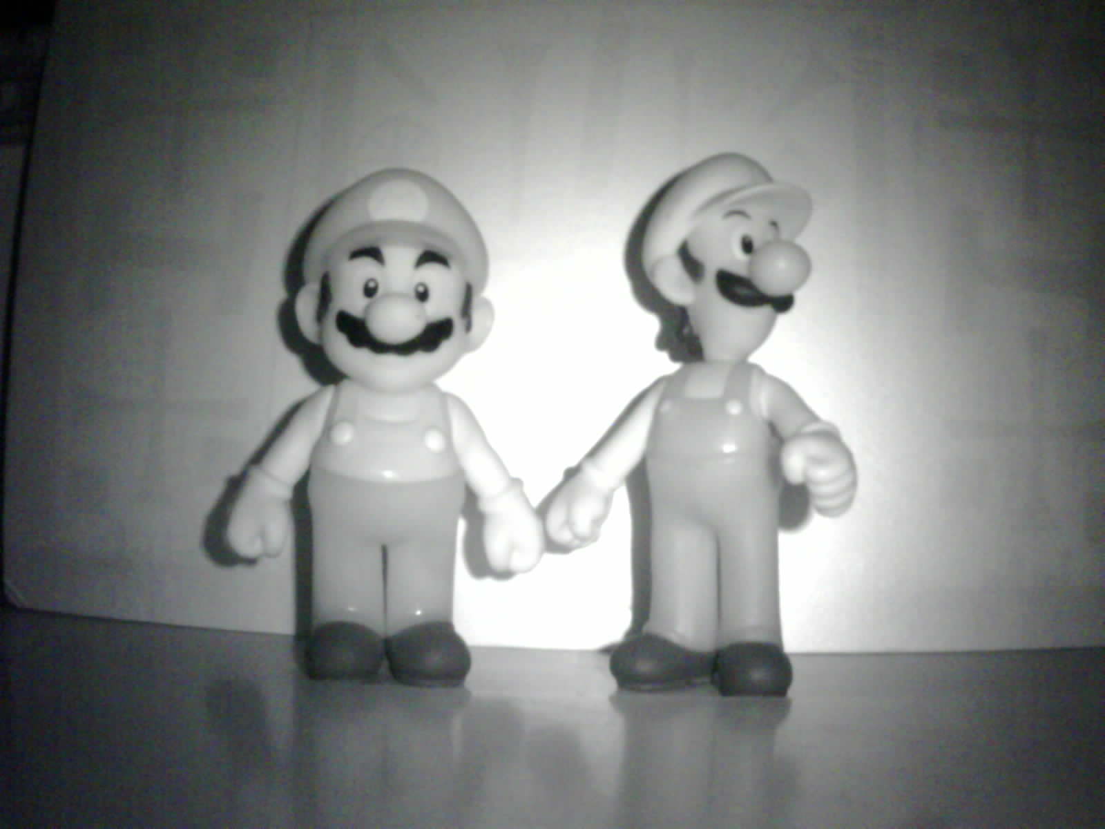
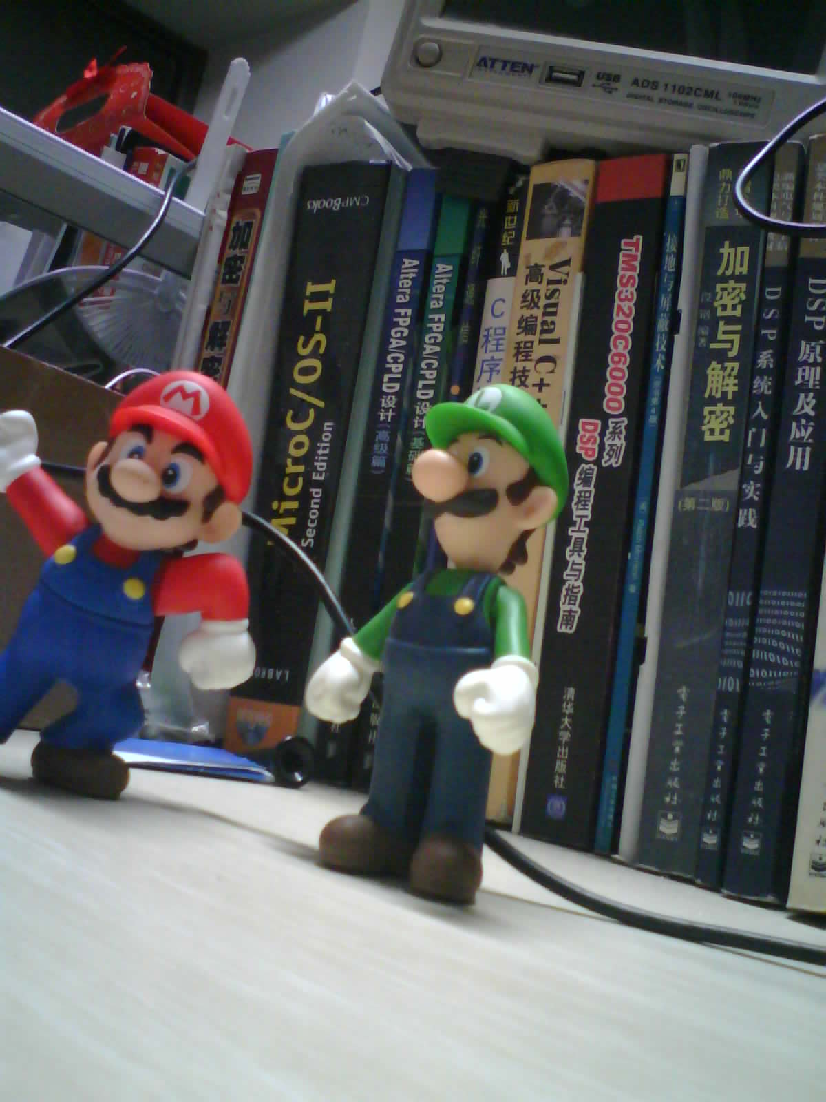
Sample Pictures Taken by OV2640
Blog

Second Generation ArduCAM Shields and Modules
Introduction ArduCAM series camera shield is a universal camera control board for Arduino. It hides the complex nature of the camera and provides the plug and play camera control interface as well as the ready to use software source code library and demo code. User can make it works in minutes without writing a line […]
Manual Exposure for OV2640
Overview ArduCAM all given examples are using auto exposure for easy use of the camera. But somethings users want to control the exposure more precisely. This article will cover how to do manually exposure to OV2640 camera.
Video
Documentation
2MP OV2640
Introduction Arducam OV2640 camera breakout incorporates Omnivision 1/4−inch CMOS active−pixel digital imaging sensor OV2640 with an active pixel array of 1632 x 1232 including border pixels. The entire system-on-a-chip (SOC) has low power requirements that is particularly suitable for IoT applications. It has onchip AEC/AGC/AWB ISP functions, and supports RAW/YUV/RGB/JPEG different output format. Key Specification […]
Software Guide
Introduction This page describle the basic control over the sensor registers using Arducam camera breakout board, it might not be able to cover all the detail register operations, but give you an insight how to adjust these settings. Sensor I2C Slave Address The OV2640 camera I2C 8-bit slave address is fixed to 0x60. With 8bit […]
Hardware Guide
Introduction This hardware guid helps for interfacing the Arducam OV2640 camera module. There are hardware USB2 or USB3(you also need Arducam Parallel Camera Adapter Board for USB3)camera shield develop boards which can well mate this camera module without designing any customize board, they can be used for fast evaluation for this camera module. Pin Definition […]
Customization
About Arducam's Customization Services:
If off-the-shelf solutions don't meet your needs, Arducam offers end-to-end custom camera design services to help you turn your ideas into real products. From early concept to mass production, we work closely with you to tailor an imaging solution to meet your unique technical requirements and product goals.
What can Arducam customize?
Sensor/Lens/circuit/interface;
Optical filter/housing/ISP, and more.
For more information about Arducam's custom design, please refer to: Arducam Custom Design