
Key Feature
- Active Array Size: 1300 x 1028
- Power Supply:
Core 1.8VDC + 10%
Analog 2.45 to 2.8 VDC
I/O 2.5V to (VDD-A+0.3V) - Power Requirements:
Active 50 mW (15 fps, no I/Opower)
Standby 30 μW - Temperature Range:
Operation -20°C to 70°C
Stable Image 0°C to 50°C - Output Formats (8-bit):
• YUV/YCbCr 4:2:2
• GRB 4:2:2
• Raw RGB Data - Lens Size: 1/4″
- Maximum Image/Transfer Rate:
SXGA 15 fps
VGA 30 fps
QVGA, QQVGA, CIF 60 fps
QCIF, QQCIF 120 fps - Sensitivity: 0.9 v/Lux-sec
- S/N Ratio: 40 dB
- Dynamic Range: 62 dB
- Scan Mode: Progressive
- Maximum Exposure Interval: 1050 x tROW
- Pixel Size 3.18 μm x 3.18 μm
- Image Area 4.13 mm x 3.28 mm
Application
- Cellular phones
- PDAs
- Toys
- Other battery-powered products
- Can be used in Arduino, Maple, ChipKit, STM32, ARM, DSP, FPGA platforms
Usage
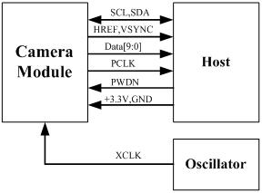
The following schematic diagram shows a basic camera-based system. The camera module is powered from a single +3.3V power supply. An external oscillator provides the clock source for the camera module XCLK pin. With proper configuration to the camera internal registers via the I2C bus, then the camera supply pixel clock (PCLK) and camera data (Data[9:0]) back to the host with synchronized signals like HREF and VSYNC.
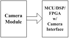
The host may have integrated camera interface like STM32F2 or STM32F4 series MCUs or ARM9/11 which has dedicated camera port, and DPS like TI TMS320DM series, as well as FPGAs that user can design special logic for camera application. The typical connection between these systems and camera modules would show as the following diagram.
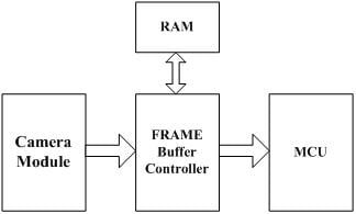
For the host that doesn’t have a dedicated camera interface, additional hardware is needed. User needs to buffer an entire frame before read them out with low-speed MCUs. For example, Arduino Camera Shield is an additional hardware that can be connected to the Arduino UNO/Mega board, user can take a photo or something like that easily. The following diagram shows the system without a dedicate camera interface.
Documents
OV9650 Sensor Datasheet
OV9650 Camera Module Drawing and Pinout
OV9650 Sensor Software Application Note
ArduCAM Shield DataSheet
ArduCAM Shield Hardware Application Note
ArduCAM Shield Software Application Note

