Hello there,
thank you for your quick response.
External trigger: usually an external trigger could be a signal that puts the trigger pin in camera module high. So i used an square wave which has a period of 25 millisecond (frequency 40 Hz), whereas it is high for 1 millisecond and low for the rest of time (24 millisecond).
Auto trigger : in auto trigger, it’s not a squre wave but a constant signal. Lets say, it puts the camera trigger pin high at time, t = 0 and stays high for the rest of the time .
I’m using an arduino uno board to produce the above described signal. Trigger pins and Gnd pins of both cameras are parallel connected with an arduino uno. To find out if the frames are synchronised, I use a digital stop watch app from smartphone and save the frames with a time stamp. Every time stamp has 4 consequent frames for each camera.
Description of Code:
Three threads are initialised, two threads for CaptureImage, each one with its own Handle (ArduCamHandle) and one thread for readImage with two Handles. In readImage function a little modification has been done. The “while” loop looks like this:
//--------------------------------------------------------------------------------------------------
beginTime = clock(); //time stamp
vector<cv::Mat> Bilder1, Bilder2;
while(_running){
if (ArduCam_avaiableImage(handle) > 0 && ArduCam_availableImage(handle2) > 0) {
rtn_val = Arducam_readImage(handle, frameData);
rtn_val2 = Arducam_readImage(handle2, frameData2);
if (rn_val == USB_CAMERA_NO_ERROR && rn_val2 == USB_CAMERA_NO_ERROR) {
int begin_disp = clock();
rawImage = ConvertImage(frameData); rawImage2 = ConvertImage(frameData2);
if (!rawImage.data || !rawImage2.data){
std::cout << “No image data \n”;
ArduCam_del(handle);
ArduCam_del(handle2);
continue;
}
Bilder1.push_back(rawImage.clone()); // To append the frames in the vector
Bilder2.push_back(rawImage2.clone());
if (Bilder1.size()==5){
if (save_flag){
for (int i = 1; i< Bilder1.size(); i++){
… // some other codes for image processing…
//Image name with a time stamp
sprintf(imageName,“Cam1/%ld_%d.jpg”, beginTime, i);
sprintf(imageName2,“Cam2/%ld_%d.jpg”, beginTime, i);
cv::imwrite(imageName, Bilder1[i]);
cv::imwrite(imageName2, Bilder2[i]); }
}
// To empty the Vectors
vector<cv::Mat>().swap(Bilder1); vector<cv::Mat>().swap(Bilder2); beginTime = clock(); //New time stamp for next image series
}
ArduCam_del(handle); ArduCam_del(handle2);
}
}
}
//------------------------------------------------------------------------
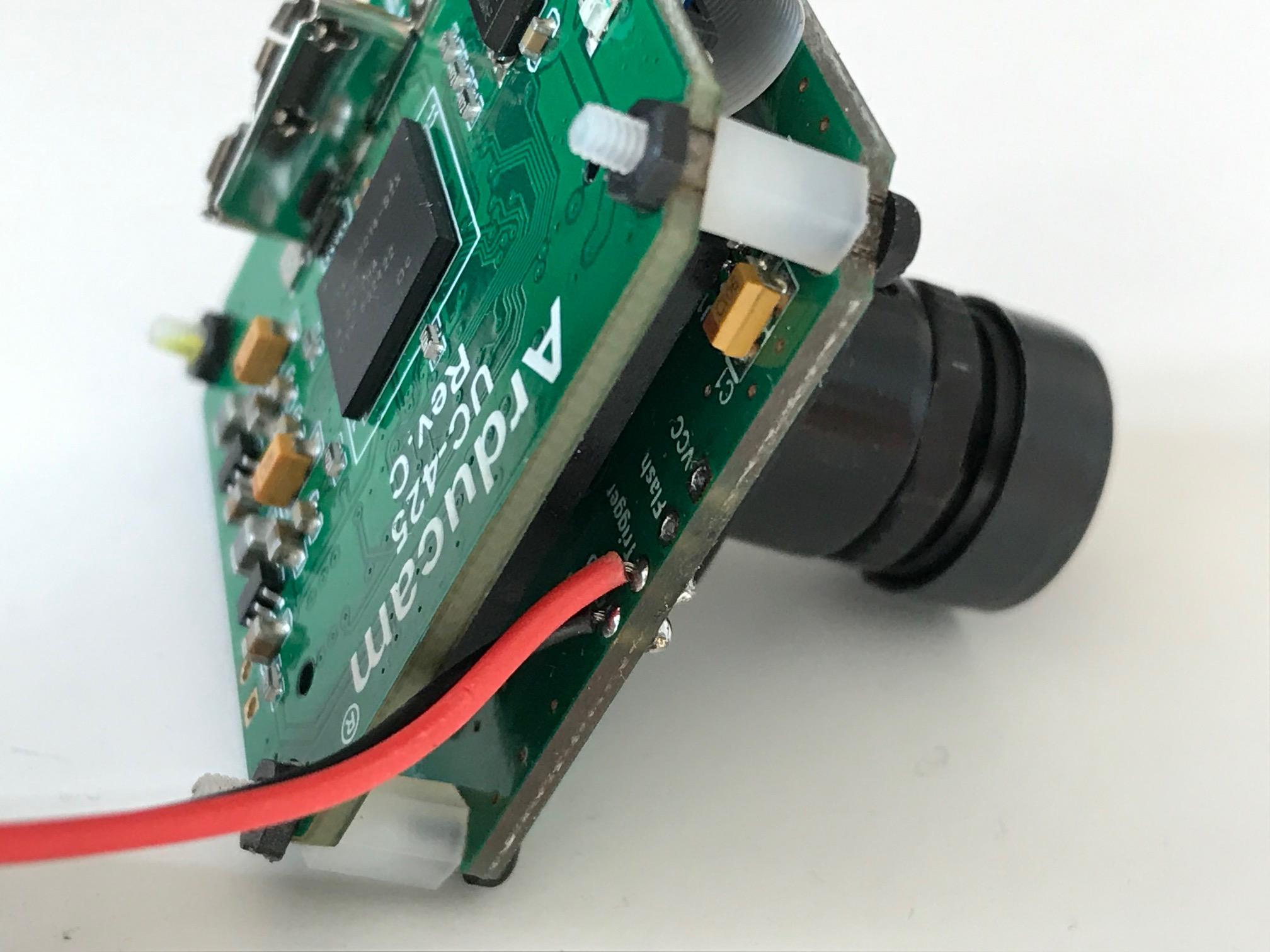
The external trigger connection with the camera module can be seen in the following picture.
Kind regards