Can you point me to a detailed list of register values for this specific camera sensor? I am interested in accessing registers related to the Frame Sync In (FSIN) and Strobe pins.
a. Since I am using a MIPI device, do the register values corresponding to Strobe in the OV7251 match the register values defined in the MIPI CSS spec under Flash Strobe?
Any guidance on these questions would be much appreciated.
The Windows GUI is designed for debugging the cameras, you can directly change the sensor register on the fly. For MIPI cameras you do need MIPI adapter board as well. Please go to the document->camera adapter board for more info about particular camera module.
You have to find the corresponding image sensor data sheet (OV7251) for register values. In terms of the FSIN function, it is very tricky, the data sheet doesn’t tell any useful information about it.
In terms of the STROBE, it is also called Flash signal.
Hi I am trying to use the FSIN and STROBE signals as they are described in the OV7251 datasheet.
I am trying to use the FSIN and STROBE pins from the Arducam board, and I have the arducam running using “./arducamstill –t 0 –m 0 –awb 1 –ae 1” I have also tried “./capture”
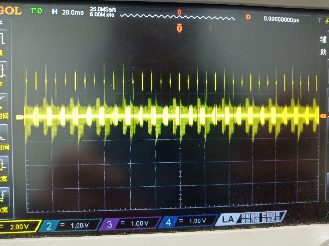
But neither of the pins output any signal corresponding to the integration of the pixal array.
Can you please explain how to get the strobe pin to output signals as described in the datasheet? The datasheet claims that the “strobe generates a pulse with a reference starting point at the time when the pixel array starts integration.”
I have been following the OV7251 datasheet and I have been trying to utilize the STROBE and FSIN pins that are advertised as part of this board’s functionality, however I have not been able to get the signals that are expected. The datasheet claims that the “strobe generates a pulse with a reference starting point at the time when the pixel array starts integration.”
I have changed (written to) register value 0x3005 to the value 0x02 and register 0x3027 to value 0x08 and still there are no pulses generated when I have the camera running using “./arducamstill –t 0 –m 0 –awb 1 –ae 1”
Will changing these register values allow me to get an output from the STROBE pin?
Why did you send register values to change for doing an external trigger? I am interested in operating the camera and having the camera driver itself control STROBE and FSIN. I am not planning on sending any input to FSIN to trigger…
Send these settings after you bring up the camera, it allows you to send trigger signal to FSIN pins to external tigger the camera, there is nothing to do with STROBE. STROBE need addtional settings to set it as output to drive your Flash light.
I changed the register values from the list you sent and there is still no external trigger or ability to use STROBE as advertised.
Here is a detailed explanation of everything I have tried changing:
I have been following the OV7251 datasheet (attached) and I am trying to utilize the STROBE and FSIN pins that are advertised as part of this board’s functionality, however I have not been able to get the signals that are expected. The datasheet claims that the “strobe generates a pulse with a reference starting point at the time when the pixel array starts integration.”
I want to be able to run the camera and have the STROBE pin output the reference signal at start of integration. I do not want to have an external trigger, although if that is the only option then I would like to learn more about the register value changes needed for that as well.
Below is the list of register values I have changed:
Can someone please contact me to explain how to get the STROBE pin to output the signals it is supposed to?
I have also been emailing [email protected] but they are still working out how to help me.
I tried to follow the steps for enabling Stobre, but register 0x3004 is not allowing a change to the 0x08. Register 0x3004 only stays to the default value of 0x00.
Register 0x3005 wrote to 0x08 without any trouble.
Currently then I have 0x3004 = 0x00 and 0x3005 = 0x08, and all other registers at default.
Please let me know what can be done. I can send my code if that helps.
Hi,
Thank you very much for getting back to me on this.
I still have a few questions:
I am having trouble writing to register address 0x3004. I have been able to write and read correctly to all other register addresses.
Does register 0x3004 need to be written strictly before register 0x3005?
For example, should I write to 0x3004 then write to 0x3005 then write to 0x3B81? Or would it work to write to them all at once?
Also, what commands are used in this software guide to test that the strobe output works? Here it does not say: https://www.arducam.com/docs/camera-breakout-board/0-3mp-ov7251-global-shutter/software-guide/
In the past I have used “./arducamstill –t 0 –m 0 –awb 1 –ae 1” to test the camera, as per instructions from this github: https://github.com/ArduCAM/MIPI_Camera/tree/master/RPI
I have been using this code as a baseline for reading/writing to register values: https://github.com/ArduCAM/MIPI_Camera/blob/master/RPI/read_write_sensor_reg.c
To follow up on this, I am still not able to write to register 0x3004.
I am able to read it- and it always stays at the value 0x00. I can’t get it to change to 0x08.
Could this be a defect in my specific camera? Is there a way to fix this?
When I reboot the camera, all of the registers are at their default value. 0x3004 and 0x3005 are at 0x00. However, I am able to change 0x3005 to 0x08.
Please let me know, thank you.
I appreciate that you all have worked on the strobe functionality so far.
Thanks,
Erika
For your reference, I am using the code below:
// Change register 0x3004 to enable strobe output
// Write to register
LOG(“Write 0x3004 exposure register to 0x08…”);
if (arducam_write_sensor_reg(camera_instance, 0x3004, 0x08)) {
LOG(“Failed to write sensor register.”);
}
uint16_t reg_val = 0;
//Read register
if (arducam_read_sensor_reg(camera_instance, 0x3004, &reg_val)) {
    LOG("Failed to read sensor register.");
} else {
    LOG("Read 0x3004 value = 0x%02X", reg_val); //Always returns 0x00...
}
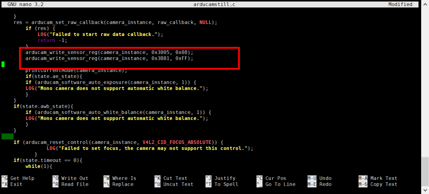
Just ignore the 0x3004 register which just the debug control register. As I have said to you in the email, you just need to set the 0x3005 to 0x08 and 0x3B81to 0xFF